
Building a Reliable Wavelength-Specific Curing Process
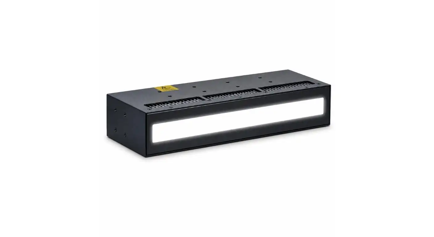
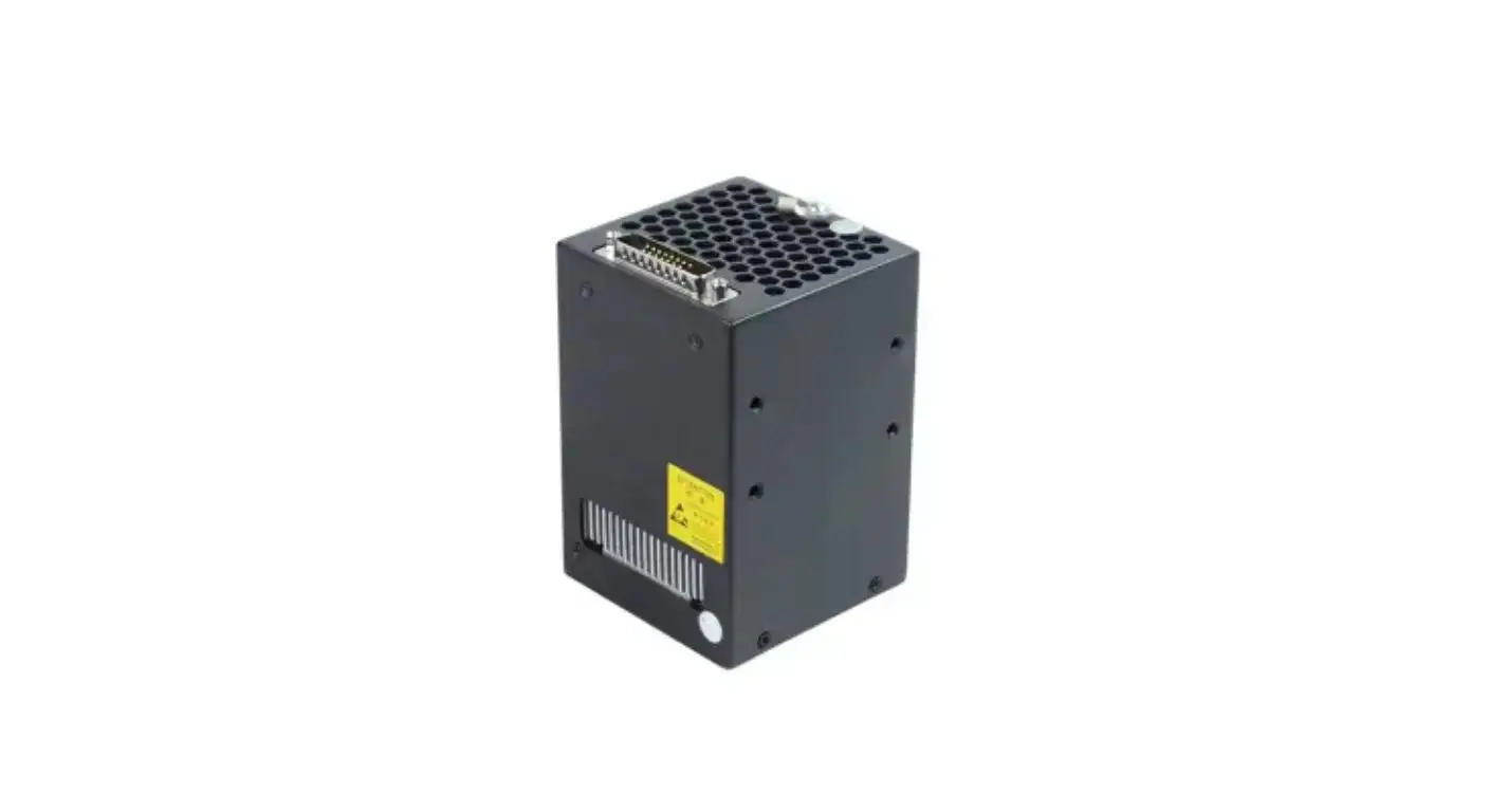
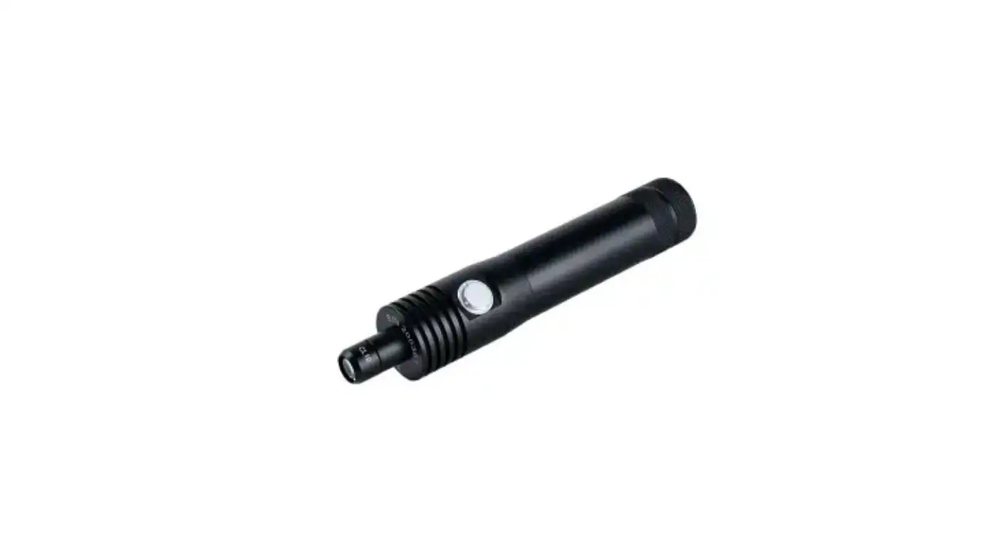
The selection of the wavelength of the UV LED is not the choice of the highest intensity, nor the general rule of one wavelength curing deeper than another. To cure reliably, the first step is to focus on the spectral response of the adhesive, ink or coating.
Wavelength-specific curing synchronizes the UV source and the photoinitiator, the substrate's transmittance, the thickness of the coating and the production speed. The UV LED Curing Light Bar comes in 4 different wavelengths: 365 nm, 385 nm, 395 nm and 405 nm, enabling engineers to choose a fixed wavelength for the process.
Start by using the Photoinitiator.
The photoinitiator absorbs the UV energy at a specific range and initiates the polymerization process. If the wavelength chosen for the selected LED light is outside of the range, longer exposure times may not yield a satisfactory cure.
Ask the supplier of the adhesive, coating or ink for its absorption data and recommended UV spectrum. The datasheet is a starting point, and not the final production setting, as the response might change with the use of different amounts of pigment and/or filler, or different thickness of application.
The absorption range can be wider for a material with multiple photoinitiators. This is not to say that all the wavelengths that are available will give the same surface cure, depth cure or adhesion.
Understand What Changes between 365 and 405 nm
Shorter wavelengths (365 nm) have more energetic photons, some longer wavelengths (395 & 405 nm) may pass through certain transparent polymers and formulated materials more readily. However, the actual curing behavior still depends on the absorption of the photoinitiator and substrate.
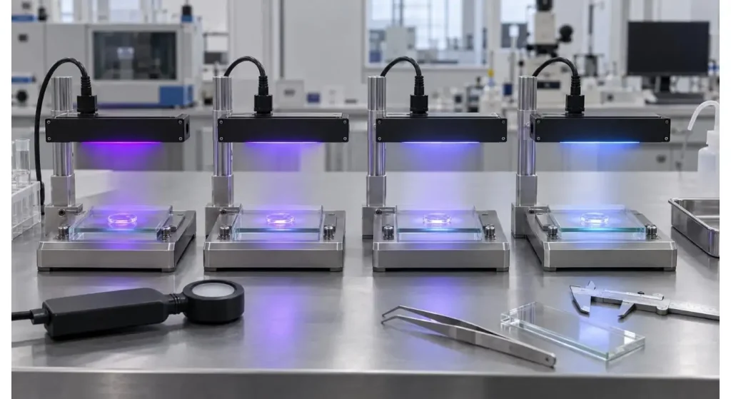
The UV LED Curing Light Bar delivers 2.5 W/cm² at 365 nm and 3 W/cm² at 385, 395 and 405 nm. The differences in outputs should be taken into account when comparing test results. Faster cure at one wavelength can be due to a higher irradiance, as well as wavelength.
Never compare models with equal exposure time if no irradiance and total dose has been measured at the curing plane.
| Selection Factor | Question to Answer | Verification Source |
| Photoinitiator | Which wavelengths are absorbed? | Material spectral data |
| Substrate | Which wavelengths pass through it? | Transmission measurement |
| Material thickness | Must energy reach below the surface? | Cross-section testing |
| Pigment or filler | Does the formulation block UV light? | Production-material trial |
| Process speed | How much exposure time is available? | Line-speed calculation |
| Temperature limit | Will the part tolerate the UV dose? | Component temperature test |
Explain in detail how substrate transmission works.
The UV light may have to penetrate a glass, plastic film or clear housing to reach the adhesive. Absorptions of part of the UV wavelength may occur in a material that can be seen with the naked eye.
Obtain or determine the transmission data for the actual substrate such as the production thickness, tint, additives and surface coating. Polycarbonate, acrylic, glass and protective films are able to transmit varying amounts of energy at varying wavelengths.
If curing is by a transparent part, measure the irradiance after the light has passed through the part. This provides a more useful measure than just at the lamp window.
This allows for the distinction between Separate Surface Cure and Cure depth.
This means that if the surface appears dry, it doesn't mean the entire material layer is cured. Absorbed energy can cause a rapid surface reaction rate, but reduce the amount of energy available further into the adhesive or coating.
Consider exposed surfaces and deepest functional surface of material. Some appropriate methods may be hardness, adhesion, solvent resistance, cross section inspection or bond strength tests.
Some will be inhibited by oxygen at the exposed surface. When satisfactory internal cure does not still result in insufficient surface tack, it may be necessary to change the formulation or process atmosphere as opposed to simply adjusting to a higher lamp setting.
Use the Linear Irradiation Area (LIA) Correctly
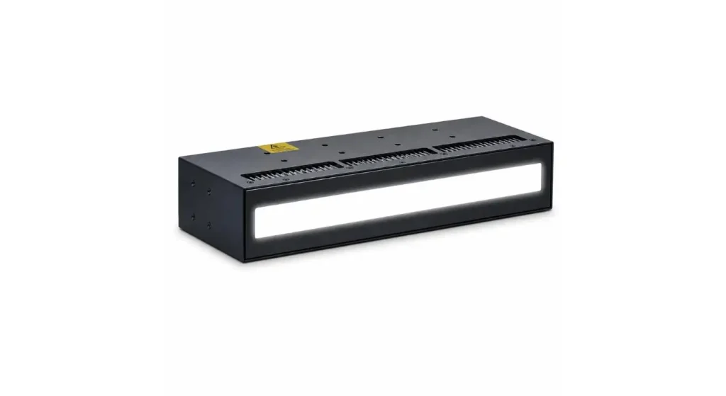
The product is capable of the irradiation area of 300 × 20 mm, with 120 LEDs. It has a long, narrow profile that is appropriate for continuous lines, narrow workpieces, edge bonding and spot curing.
The working distance affects the irradiance, coverage and uniformity. An increased distance can increase the useful light field, but decrease the energy of the light reaching the material. A shorter distance will result in higher irradiance and more sensitivity of alignment.
Repeat the above steps for the output at 300 mm length at the working distance. Take measurements at the center, at each end, and at various points in between before creating the recipe for the production.
Additional information is given on curing area selection and integration with the wider UV LED area curing range.
Coordinate the speed of production with Match Dose.
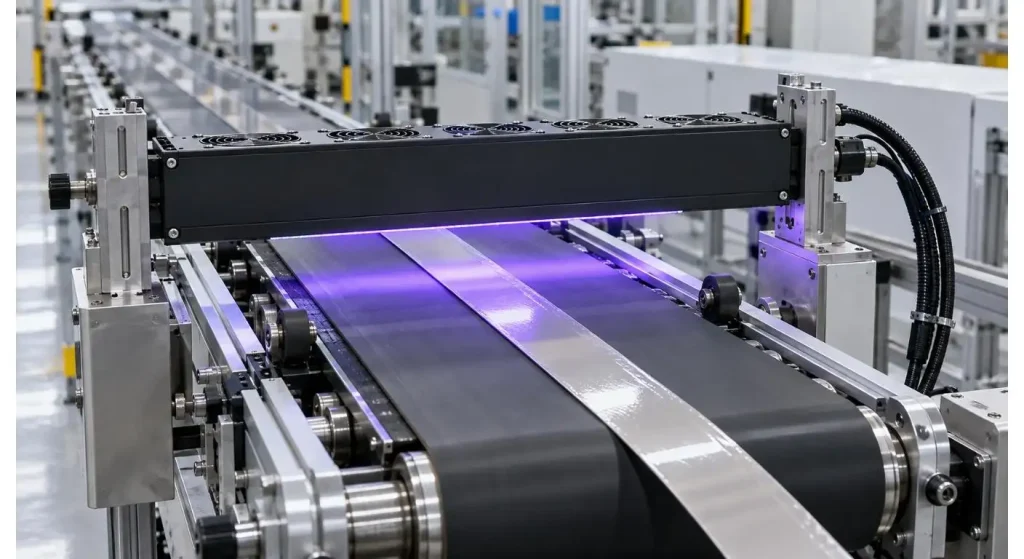
UV dose is dependent on the amount of UV irradiance to which the material is exposed, and the duration that the material is exposed to the lamp. For a conveyor or web process, the longer the speed of the line, the shorter the exposure time.
Operate the material at minimum, normal and maximum production speeds. Write down wavelength, irradiance, working distance and line speed for each of the trials.
It is not limited to a single recipe, but rather it should have acceptable high and low settings. This allows production teams to deal with normal variation without going into under-cure or over-exposure.
Use a cooling controller to manage the output from the sun collector.
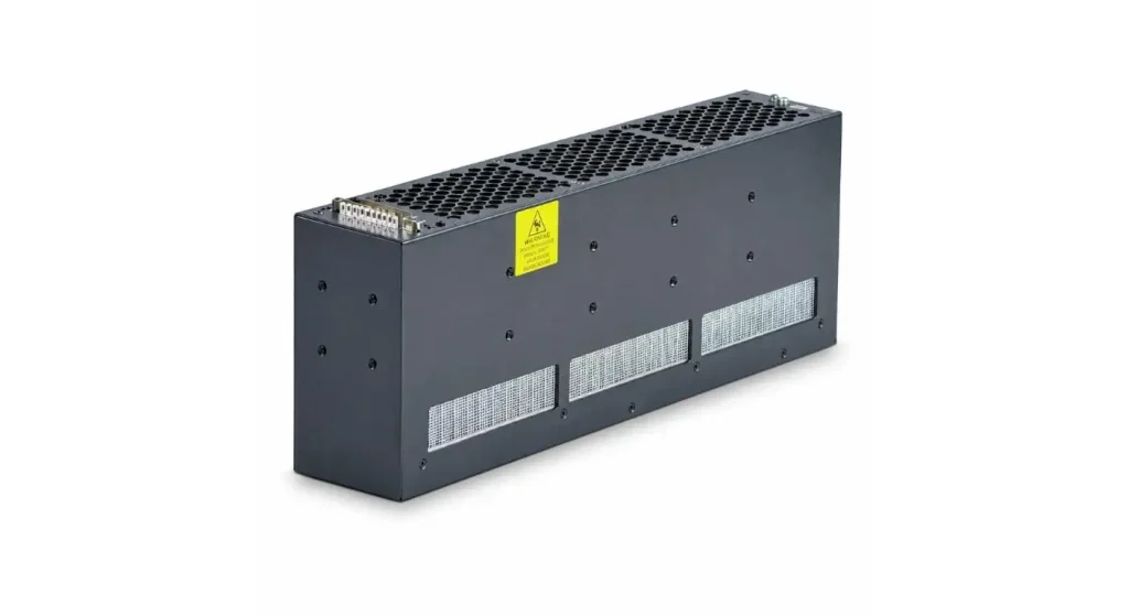
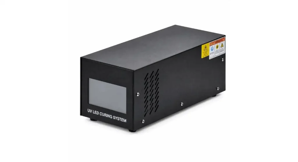
When running, the light bar cools the heat by using fan cooling. The stable cooling is important as it influences output stability and service life of the LED.
Provide adequate space around air inlet/exhaust. Do not point warm exhaust gas at another UV light or make no ventilation plans for UV enclosure.
After the system has reached normal operating temperature, measure the irradiance. Nothing is guaranteed if the test is successful during the cold-start phase, but not during a long production run.
Construct a Wave Length Comparison Experiment.
If the ideal wavelength is not known, consider experimental models in controlled conditions. Apply to the material batch, substrate, coating thickness and acceptance tests.
The intensities shown are different, so changes in exposure conditions must be made so that the comparisons relate to the dose itself, and not to the amount of time of exposure. Consider cure speed as well as adhesion, hardness, and appearance and temperature of the substrate.
| Trial Record | Controlled Condition | Result to Compare |
| Wavelength | Selected LED model | Material response |
| Measured irradiance | Actual curing plane | Delivered UV power |
| Exposure time | Fixed or dose-adjusted | Cure speed |
| Applied thickness | Same material layer | Cure depth |
| Substrate | Same type and thickness | Transmission effect |
| Functional test | Same method and limit | Final cure performance |
Add the Selected Wavelength to the Production.
After the wavelength is approved, ensure the control of the exact equipment model and configuration. Changing from a 395 nm unit to a 405 nm unit with the same physical form should be considered a process change.
The small UV LED Curing Light Bar can be used in conveyors, assembly stations and in customized curing equipment. To maintain the validated working distance, angle and airflow, integration should be done.
OEM/ODM UV LED services are offered by UVET for projects that need special mounting and/or control or optical configurations.
Keep an eye on the Validated Spectrum and Dose.
The normal check should be performed by cleaning the optical window, checking the fan and measuring the irradiance. Use a radiometer in the desired range of wavelengths.
Note the identity of the equipment used and the conditions under which the measurements were taken so that the results can be compared. For changes in the material formulation, substrate, lamp or fixture speed or line speed, review if the curing process requires revalidation.
Conclusion
Wavelength specific curing by the LED spectrum links the entire Material system. Wavelength labels and maximum intensity aren't enough to determine which choice is correct.
Start with photoinitiator absorption, check the transmission of the substrate, and measure the dose and/or function the candidate wavelengths. This means that instead of making assumptions, it's a repeatable process based on material response.
FAQs
Q1. For deep curing, is 365 nm the optimal wavelength?
No. Cure depth is related to absorption, formulation, thickness and transmission of the substrate. In order to find out which wavelength provides energy throughout the entire thickness of the material, it must be tested practically.
Q2. Is there a lamp that will cure ALL UV adhesives at 405 nm?
No. The photoinitiator in the adhesive should be able to react to the 405 nm light. Test the material prior to the receipt of the material supplier's spectral data.
Q3. Can the wavelength based models be compared with an equal number of exposures?
Not reliably. Both model and dose differences exist, and comparisons made on the basis of measured dose and with identical material conditions.
Q4. Why is a UV-coating still sticky after being coated?
This may be due to a mismatch between the spectrum, insufficient dose, oxygen inhibition or an excess of coating. A review of the cure condition and formulation should be done together.
Q5. When is a wavelength specific process revalidated?
Revalidation should be considered when the UV wavelength is changed, material formulation, substrate, coating thickness, working distance or production speed is changed.
Share on Social:


- PREV: Building a Reliable UV Curing Process for Medical Device Assembly
- NEXT: Null
