
COB UV LED Module Integration: Key Design Factors for Industrial Curing Systems
A high power COB UV LED Module could be listed on a specification sheet to have a tremendous amount of radiant output, but not work well when put into a small curing machine.
Thermal resistance, electrical driving conditions and the method of delivery of the emitted light to the working surface are the differences often.
When it comes to picking a COB module, it's not just about the highest wattage for UV equipment manufacturers. The module should function successfully in the total optical, electrical and thermal system.
Knowing these needs in the beginning can help avoid costly re-design when equipment is being developed.
What is COB UV LED Module?
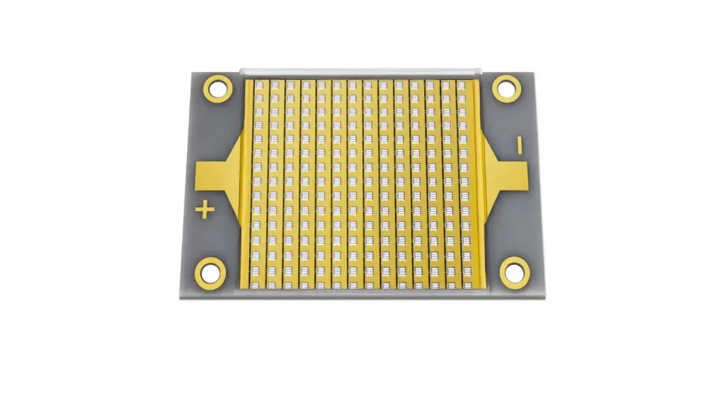
Chip-on-Board (COB) is the acronym for COB. In this packaging technology, a plurality of LED chips are attached to the same substrate to form a compact high density light source.
A COB module is different from the arrangement with numerous individually-packaged LEDs by having all the emitting chips packed into a single assembly.
Such architecture can enable small size of equipment and ease in mechanical integration.
But with high chip density, the construction and thermal design of the substrate becomes even more critical.
UVET provides various COB UV LED modules for manufacturers who are interested in creating industrial curing lights, printing systems and precision irradiation equipment.
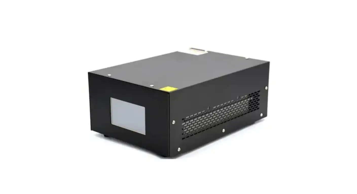
The COB module is just a component of the complete curing system. It still needs to be engineered around for power control, cooling, optics and protective housing.
Know about Chip Density and Module Construction.
The number of LED chips is only one factor in achieving the potential light output and thermal loading of the module and does not indicate curing performance.
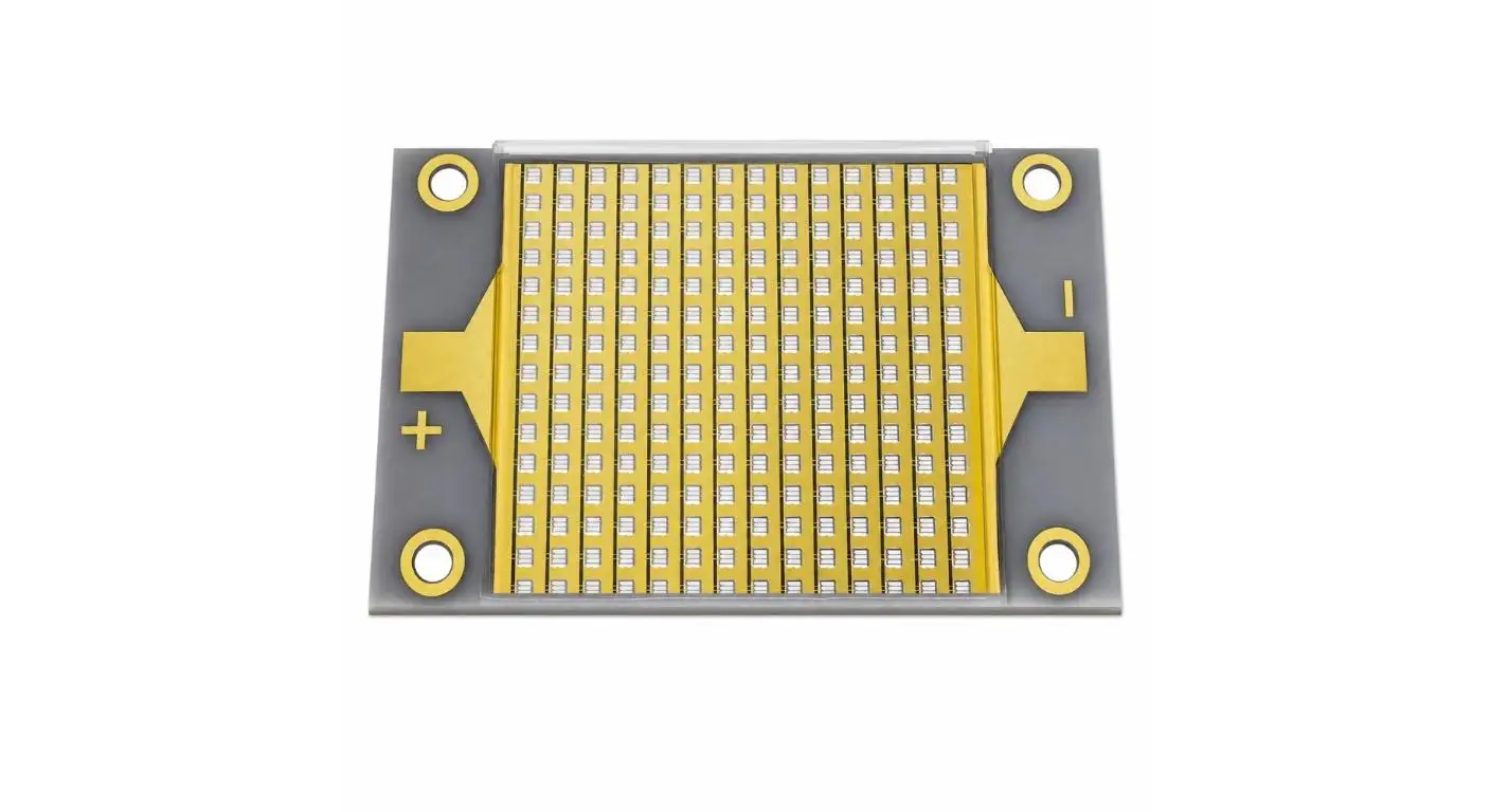
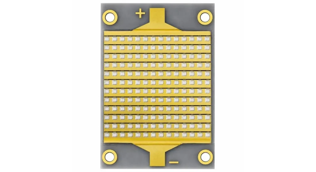
UVET's COBUN-196C is a 50 × 30 mm COB module with 196 UV LED chips of type SEOULVIOSYS UV-A.
Compact arrangement for a concentrated emitting surface for equipment where space to install is limited.
The module additionally features a flat optical window which offers a well-defined interface for external optics or protective structures.
For the package, the engineers will consider the placement of the chips, size of the emitting area, mechanical mounting points and optical accessibility.
The only time a greater number of chips is helpful is when the electrical and thermal design permits them to be used within certain limits.
The importance of MCPCB Thermal Management
Only part of the electrical input into high power UV LED chips is converted into optical radiation. Any surplus energy generates heat which needs to be extracted.
Optical performance, wavelength and long-term reliability may be impacted with increasing junction temperature.
The COBUN-196C adopts a method of direct bonding chips to a metal core printed circuit board (MCPCB) to help reduce the thermal resistance between the chips and printed circuit board.
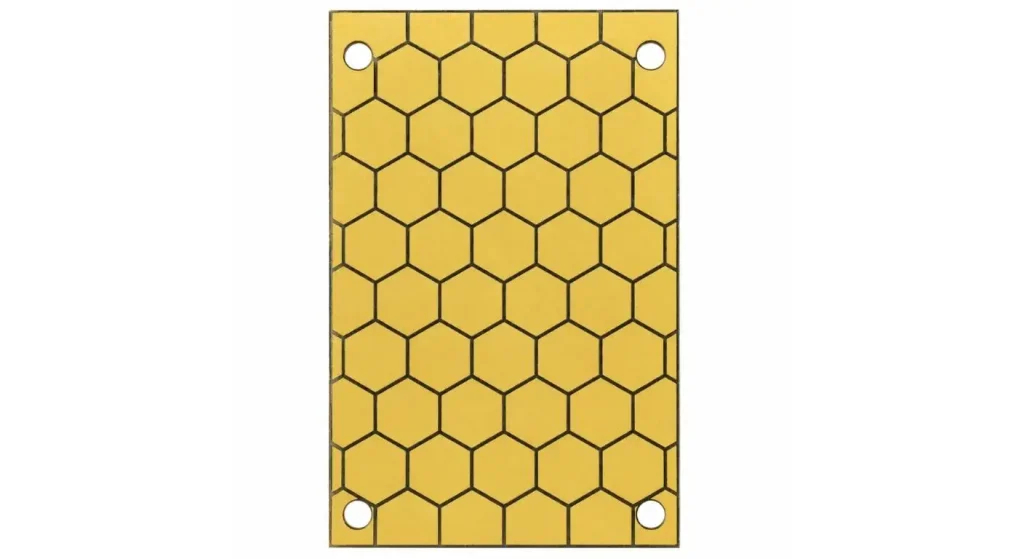
This construction will improve the heat-transfer path, but it does not remove the need for external cooling.
They have to take into account heatsink contact, heatsink interface materials, coolant capacity or airflow, and maximum operating temp for the engineer.
The actual electrical load and duty cycle should be considered to test the cooling design; don't expect the MCPCB to be enough.
Differentiate between Radiant Flux and Electrical Power
When power measurement terms are used interchangeably, then they can be misleading.
The total optical radiation emitted by a source is called radiant flux and is measured in watts.
Electrical input power does not equal radiant flux as it is the power used by the LED assembly.
The optical power per unit area received at a point is called the irradiance, typically measured in watts per square centimeter (W/cm2).
The 365 nm is listed as having 175 W radiant flux, and the 385 nm, 395 nm and 405 nm are listed as 210 W radiant flux, according to UVET's High Power UV COB LED Module.
The engineers should verify the operating current, cooling requirements and measurement conditions prior to using these figures in system calculations.
High total radiant flux does not necessarily imply high (or uniform) irradiance at the curing surface.
| Parameter | Information to Confirm | Required Evidence |
| Radiant flux | Optical output and test conditions | Optical test report |
| Forward voltage | Rated operating range | Electrical specification |
| Drive current | Nominal and maximum limits | Driver requirements |
| Thermal resistance | Junction-to-mount heat path | Thermal data |
| Peak wavelength | Spectral output | Spectrum report |
| Mounting dimensions | Mechanical compatibility | Engineering drawing |
Connect the Driver with the LED Module.
For a COB UV LED Module to operate, it is necessary to use the electrical driver that matches with its voltage, current and control specifications.
It is possible that incorrect driving conditions lead to a decrease in optical stability and/or to higher heat generation and/or to damage of the LED assembly.
Before designing the power-supply, engineering teams should verify the engineering allowable operating current, forward-voltage range and allowable method of control.
High-power LED installations are most frequently designed to be constant-current driven and are protected against electrical fault and overcurrent conditions.
If the machine needs the UV output to be adjustable, it's worth looking at the repeatability of the chosen driver and its dimming technique.
The entire operating spectrum, starting, long duration of operation and switching cycles, must be considered in the design of power supplies.
Design Optical System Based on the Application
COB packaging delivers concentrated light source with the final irradiation pattern being dependent on the additional optical design.
Different reflectors, lenses and working distance and combinations of multiple modules can change the distribution of light.
A wide industrial exposure area might need an additional optics or multiple modules, depending on the application, a compact source can be considered for focused curing applications.
Also losses due to protective windows and secondary components should be taken into account.
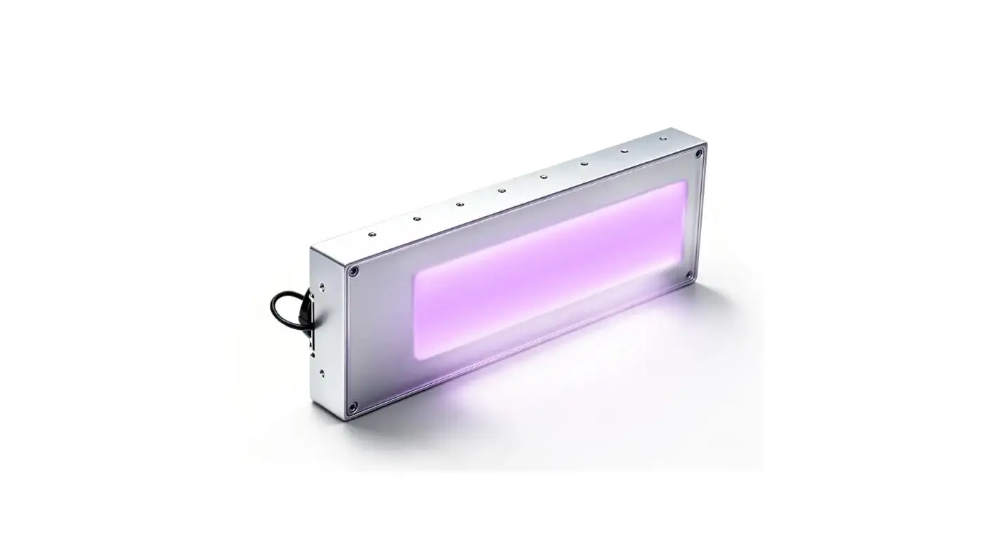
An example of the use of COB technology in a larger industrial curing assembly is UVET's UV LED Lamp for Inkjet Printing.
Not only the bare module output should be considered, but also the finished optical system at the aimed working distance should be evaluated by OEM developers.
Create a reliable OEM integration process.
The mechanical, electrical, optical and thermal engineering teams will need to coordinate with each other when integrating a COB UV LED Module into an industrial equipment.
Secure mounting of the module should be achieved with good thermal contact.
Electrical connections must be safeguarded from strain, incorrect polarity and unintended contact.
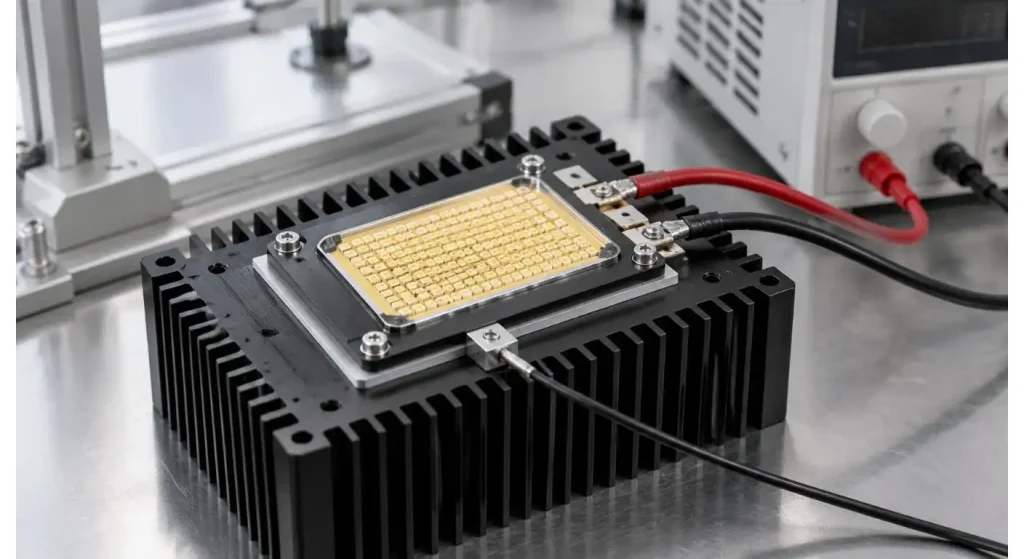
Suitable UV shielding, interlocks and operating controls to protect personnel should also be included in the system.
UVET's UV LED Modules range includes a variety of package variants, suitable for different UV equipment development.
Manufacturers should verify technical drawings and operating limits, availability of samples and engineering support before finalizing a design.
Ensure that performances are correct prior to mass production.
The module and system levels should be evaluated by means of a prototype.
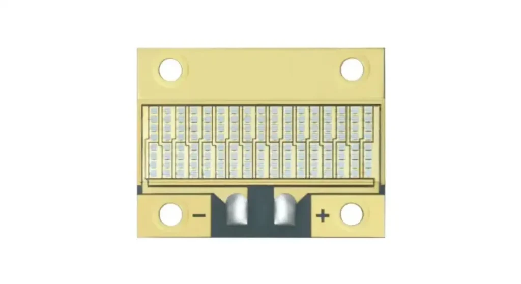
The module testing can be electrical parameters, optical output, wavelength, operating temperature etc.
The system level testing should cover the following: irradiance distribution; cooling stability and performance (after repeated or long period operation).
The use of appropriate calibrated UV meters and documented operating conditions shall be used for measurement.
There is also a need to investigate if an optical output change occurs after thermal stabilization for the engineers.
Consistent assembly methods and incoming inspection procedures help minimise the variation in performance between units for commercial production.
| Test Stage | Verification Method | Acceptance Focus |
| Electrical startup | Voltage/current monitoring | Within rated limits |
| Thermal stabilization | Temperature measurement | Stable thermal conditions |
| Optical output | Calibrated UV measurement | Meets specified output |
| Beam distribution | Irradiance mapping | Required coverage |
| Duty-cycle test | Repeated operation | No unacceptable drift |
| Pilot assembly | Multi-unit inspection | Consistent build quality |
Conclusion
While the number of chips or the rated radiant flux may be the most obvious factors for determining the success of a COB UV LED Module as the building block for high-power industrial UV curing equipment, much more is required to achieve a successful integration.
There is a requirement for thermal management, electrical driving and optical design to work together to ensure reliable operation.
OEM manufacturers can test the entire system prior to production and validate part specifications to create more consistent and maintainable UV curing solutions.
FAQs
Q1. What is COB UV LED Module?
It is a UV light source comprising a number of LED chips directly mounted on a common substrate. The construction enables compact high density optical output.
Q2. What is the reason for using MCPCB in high power UV COB module?
An MCPCB helps to deliver a better heat conduction path from the LED chips. There is a need for external cooling to achieve appropriate operating temperatures.
Q3. Would it be correct to say that radiant flux equals electrical power?
No, radiant flux is emitted optical power and electrical power is consumed by the module.
Q4. Which wavelength can COB UV LED modules be used for?
The standard industrial wavelength is 365nm, 385nm, 395nm and 405nm. The type of selection varies according to the material and its application.
Q5. What kind of tests should OEM manufacturers do before integration?
They should check such things as electrical operating limits, temperature, optical output, irradiance distribution and performance under the proposed duty cycle.
Share on Social:


- PREV: Selecting a UV LED Printing System for Reliable Ink Curing
- NEXT: Null
