
How Mobile UV Solution Supports Flexible and Low-Volume Manufacturing
High-mix production rarely fails because curing is too slow. More often, the problem is that the curing equipment is too rigid for frequent product changes.
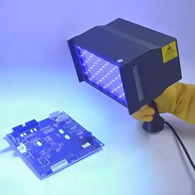
Prototype builds, pilot runs, repair batches, customized assemblies, and low-volume production may involve different part sizes, coating locations, adhesive geometries, or access directions within the same shift. Under these conditions, a dedicated conveyor or fixed curing station can create unnecessary fixture changes, idle equipment, and long setup cycles.
A Mobile UV Solution addresses this problem by moving the UV source to the process location. The engineering challenge, however, is to preserve repeatability while gaining flexibility.
Why Flexible Production Needs a Different Curing Strategy
In mass production, UV curing is normally optimized around one stable combination of:
• Fixed part geometry
• Fixed lamp-to-part distance
• Fixed conveyor speed
• Fixed fixture position
• Predictable takt time
Low-volume manufacturing breaks this stability. Parts may be too large for a chamber, bonding areas may face different directions, or only a small repaired section may need exposure.
A Mobile UV Solution becomes useful when manufacturers need to cure the required area without redesigning the entire workstation around every new SKU.
This is especially relevant for:
• Engineering validation and pilot production
• Precision bonding and sealing
• Automotive coating repair
• Wood, veneer, and composite finishing
• Optical and electronic assemblies
• Localized rework on finished products
The technical objective is therefore not simply portability. It is controlled UV delivery under changing production conditions.
Process Repeatability Depends on Exposure Geometry
A major concern with any handheld or movable UV source is operator variation.
Even when the LED output remains unchanged, the dose received by the part can vary because of:
• Lamp-to-surface distance
• Exposure angle
• Dwell time
• Hand movement
• Overlap between adjacent exposure zones
For example, holding the lamp perpendicular to a flat surface produces a different energy distribution from curing the same area at an oblique angle. Increasing distance can enlarge the illuminated footprint while reducing the energy density reaching the substrate.
A production-ready Mobile UV Solution should therefore convert operator movement into defined process conditions.
Recommended Process Controls
A low-volume curing SOP should specify:
• Nominal working distance and acceptable tolerance
• Maximum angular deviation
• Exposure time per position
• Scanning direction
• Overlap percentage between passes
• Cooling interval if required
• Acceptance criteria after curing
Simple spacers, positioning brackets, templates, or distance guides can significantly reduce operator-dependent variation without turning the mobile system into a fixed machine.
Coverage Efficiency Matters More Than Lamp Size
One of the most useful specifications for flexible curing is the relationship between the effective exposure field and the actual process area.
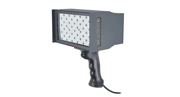
UVET's portable UV LED configuration provides a 150 × 80 mm irradiation field, equivalent to a nominal illuminated area of:
150 mm × 80 mm = 12,000 mm² = 120 cm²
This matters because low-volume production often involves medium-sized coating or bonding zones that are too large for a point source but too small to justify a full conveyor system.
Consider a repair area of approximately 300 × 160 mm. In ideal geometric terms, a 150 × 80 mm field can cover that surface in roughly four exposure positions before accounting for overlap.
In production, some overlap should normally be retained to avoid low-dose seams between adjacent positions. This creates a more realistic relationship:
| Process Factor | Effect on Mobile UV Curing |
| Larger exposure field | Fewer lamp positions |
| Greater required overlap | Higher total curing time |
| Irregular geometry | More operator repositioning |
| Small localized repair | Higher benefit from mobile curing |
| Large continuous sheet | Conveyor system may be more efficient |
This is why a Mobile UV Solution should be selected according to usable coverage per cycle rather than physical lamp dimensions alone.
Thermal Stability Influences Optical Stability
UV LED systems generate less radiant heat than conventional mercury-based sources, but the LED module itself still produces thermal energy.
If the LED junction temperature increases excessively, optical output can drift and component life can be affected. Thermal management therefore becomes a process-control issue rather than simply an equipment-protection feature.
UVET uses fan cooling in its portable system. For low-volume production, this supports several practical advantages:
• More stable UV output during repeated exposures
• Reduced heat accumulation inside the LED module
• Improved suitability for intermittent and repeated repair work
• Lower radiant thermal loading on sensitive substrates
This is particularly useful for wood, veneer, composites, coated plastics, and optical assemblies where unnecessary heat can cause distortion, surface damage, or dimensional change.
Operators should also keep air inlets and outlets unobstructed. Dust accumulation or blocked airflow can reduce cooling effectiveness even when the lamp still appears to function normally.
Mobile UV Solution vs. Production Alternatives
Flexible manufacturing does not make fixed UV systems obsolete. Each architecture solves a different production problem.
| System | Production Strength | Main Engineering Constraint |
| Mobile UV Solution | High-mix, repair, pilot runs, large assemblies | Operator motion must be controlled |
| Fixed UV LED | Repeatable workstation processing | Requires stable product geometry |
| Conveyor UV | High throughput and continuous production | Higher integration and floor-space demand |
| Spot UV | Precise small-joint curing | Low coverage for larger surfaces |
The decision should therefore be based on production economics and geometry.
A conveyor may be superior for thousands of identical parts per shift. A Mobile UV Solution is often more rational when the factory processes several designs in quantities of tens or hundreds and the curing location changes frequently.
Matching Mobile UV Output to Real Production Work
UVET's portable platform is available with 365, 385, 395, and 405 nm LED configurations. The 365 nm version reaches approximately 300 mW/cm², while selected longer-wavelength configurations are specified around 350 mW/cm².
These figures become meaningful only when translated into an actual production process.
For example, at a measured workpiece irradiance of 300 mW/cm²:
• 5 seconds delivers approximately 1.5 J/cm²
• 10 seconds delivers approximately 3.0 J/cm²
• 15 seconds delivers approximately 4.5 J/cm²
The required value depends on the adhesive, coating thickness, pigment loading, photoinitiator system, substrate transparency, and acceptance criteria.
For this reason, process engineers should define a curing window through actual validation rather than assuming that maximum output automatically equals maximum productivity.
Building a Repeatable Mobile UV Workflow
A robust Mobile UV Solution should be integrated into the manufacturing process through measurable checkpoints.
Before Production
Confirm:
• Material compatibility
• Required wavelength
• Target dose range
• Allowable substrate temperature
• Curing area and access direction
During Production
Control:
• Lamp position
• Dwell time
• Scan pattern
• Overlap
• Cooling airflow
During Maintenance
Check:
• Optical window cleanliness
• Fan operation
• Cable and connector condition
• Irradiance drift using an appropriate radiometer
For low-volume manufacturing, these controls often provide sufficient repeatability without the cost and inflexibility of a fully automated curing cell.
Validation Before Releasing the Process
The curing system should be validated on the actual production material, not only on a supplier sample.
Depending on the application, validation can include:
• Lap-shear or bond-strength testing
• Coating hardness
• Tack-free condition
• Adhesion testing
• Surface temperature measurement
• Visual inspection for under-cured edges
• Operator-to-operator repeatability
Electrical safety, EMC documentation, UV exposure protection, CE, RoHS, and other market-specific compliance documents should also be confirmed directly with the supplier for the required destination market.
When a Mobile UV Solution Makes Better Manufacturing Sense
A Mobile UV Solution is most valuable when flexibility, access, and product variation matter more than maximum automated throughput.
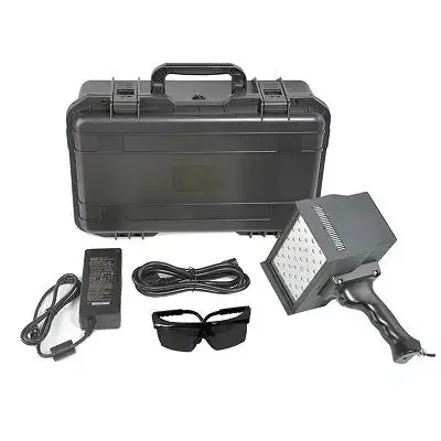
UVET's portable UV LED platform combines a 150 × 80 mm irradiation area, 365–405 nm wavelength options, approximately 300–350 mW/cm² output depending on wavelength, fan-cooled thermal management, instant LED activation, and low radiant heat characteristics. These features make the system suitable for pilot production, localized coating, repair, bonding, and other flexible manufacturing processes where a dedicated curing line would be inefficient.
For manufacturers evaluating mobile UV curing, UVET can help review the actual part geometry, curing chemistry, required exposure area, and production cycle before selecting a suitable Mobile UV Solution.
FAQs
Q1. What manufacturing applications are compatible with UVET's Mobile UV Solution?
UVET's Mobile UV Solution can be useful for manufacturing applications that require high-mix and low-volume production, prototype builds, small production runs, localized coating and adhesive bonding, repairs, and assemblies that are difficult to move to a fixed UV curing system.
Q2. Does UVET's Mobile UV Solution offer any wavelengths for UV curing?
For mobile UV curing, UVET offers configurations of portable UV LED's at 365nm, 385nm, 395nm, and 405nm. For the selection of the appropriate UV curing wavelength, consideration should be given to the absorption properties of the adhesive, coating, ink, or resin.
Q3. What irradiation area does UVET's portable UV curing system have?
UVETs portable system has an irradiation area of approximately 150 x 80 mm, or roughly 120 cm² of irradiation. This area is suitable for most applications such as coatings, repairs, sealing and bonding.
Q4. What UV intensity can UVET's Mobile UV Solution provide?
The 365 nm configuration provides an irradiance of approximately 300 mW/cm², and it is stated that some longer wavelength configurations are around 350 mW/cm². The actual irradiance should be measured at the working distance.
Q5. Is UVET’s Mobile UV Solution appropriate for use with sensitive materials?
Yes. Compared to many conventional UV lamp systems, UV LED technology produces less infrared radiant heat, and as such, is useful for various applications that utilize heat sensitive materials such as wood, veneer, composites, coated plastics and some optical components. It is still important to verify the substrate temperature during the process development.


