
Precision Assembly Curing for High-Accuracy Optical Bonding
In high-accuracy optical assembly, the bonding step can become the final source of positional error. A lens, prism, filter, sensor, or optical fiber may be correctly aligned before exposure, yet polymerization can still introduce decenter, tilt, focal shift, or coupling loss.
For this reason, Precision Assembly Curing should be treated as a dimensional-control process rather than a simple adhesive-hardening step. The curing strategy must preserve the position established during alignment while controlling bondline deformation, asymmetric shrinkage, fixture loading, thermal drift, and shadowed regions.
This is especially important in camera modules, laser optics, photonics, optical sensors, AR/VR assemblies, and compact optoelectronic modules where micrometer-scale displacement can affect final optical performance.
Why Alignment Can Shift During Precision Assembly Curing
UV-curable adhesives change from a low-modulus liquid into a cross-linked polymer. During this transition, shrinkage and modulus growth occur simultaneously.
A simplified dimensional relationship is:
ΔL ≈ L × S
where L is the effective adhesive dimension and S is the effective shrinkage strain.
In practice, however, the displacement is strongly influenced by the joint structure. A thick asymmetric adhesive fillet can pull differently from a thin, symmetric bondline even when the same adhesive is used.
Typical post-cure defects include:
• Lens decenter or angular tilt;
• Focal plane displacement;
• Reduced MTF;
• Prism angle deviation;
• Wavefront distortion;
• Reduced fiber coupling efficiency;
• Drift after thermal cycling.
The engineering target of Precision Assembly Curing is therefore not maximum cure speed. It is minimum positional change between aligned, tack-cured, fully cured, and fixture-released states.
Bondline Geometry Often Matters More Than Nominal Adhesive Strength
Optical bonding joints should be evaluated as mechanical structures.
Three factors are especially important:
Bondline Thickness
A thicker adhesive layer provides more compliance, but also introduces more polymer volume that can change dimension during cure. Excessively thin joints, however, may create high local stress or poor adhesive distribution.
The optimum thickness therefore depends on:
• Adhesive viscosity;
• Substrate flatness;
• Required gap;
• Expected cure shrinkage;
• Thermal expansion mismatch;
• Mechanical load after curing.
Fillet Symmetry
If adhesive is deposited predominantly on one side of a lens or sensor frame, shrinkage force can act off-axis. For Precision Assembly Curing, symmetric adhesive placement often reduces net rotational moment.
Joint Constraint
A rigid metal holder restricts adhesive contraction more strongly than a compliant polymer carrier. The same adhesive can therefore produce different residual stresses in different housings.
This is why adhesive selection and fixture design cannot be separated from the Precision Assembly Curing process.
Cure Sequence Controls When the Assembly Becomes Mechanically Locked
One of the most useful process variables in high-accuracy bonding is when and where the adhesive is allowed to become rigid.
A one-step full cure can rapidly lock the entire bondline, but it may also freeze cure-induced stress before the assembly has time to relax.
A more controlled sequence is:
Active Alignment → Symmetric Tack Cure → Optical Recheck → Final Cure → Fixture Release → Final Measurement
The tack stage should provide enough stiffness to prevent movement during handling, but it does not need to complete polymerization.
This separation provides two important benefits:
• Optical performance can be checked before the final cure;
• The final exposure no longer has to perform alignment locking and complete polymerization simultaneously.
For demanding Precision Assembly Curing applications, several smaller tack points around a component may also be preferable to curing one side first. A balanced cure sequence reduces asymmetric pulling forces.
Spot, Controlled-Area, Chamber, and Dual Cure Solve Different Problems
The curing architecture should follow the optical assembly geometry rather than a generic equipment preference.
| Curing Method | Best Fit | Key Engineering Limitation |
| Spot curing | Fiber alignment, localized lens fixation | Limited coverage; sequential points may create asymmetric stress |
| Controlled-area curing | Lens modules, sensors, filters | Requires good UV access across the joint |
| Chamber curing | Multi-side or batch assemblies | Higher integration complexity |
| UV + thermal dual cure | Hidden adhesive under opaque structures | Longer overall process |
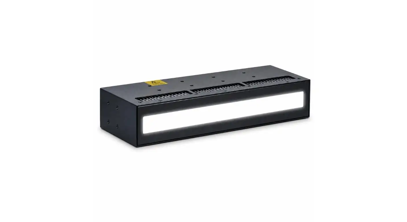
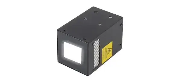
UVET's curing platform provides a 50 × 30 mm irradiation area, which is useful for compact optical and optoelectronic assemblies where several bond points must be exposed simultaneously.
Instead of curing four adhesive points around a sensor or lens holder one after another, a controlled-area source can expose multiple locations during the same cycle. This can reduce sequence-induced imbalance when the assembly geometry permits direct irradiation.
Shadowed Regions Should Be Treated as a Joint-Design Problem
A common Precision Assembly Curing failure occurs when visible adhesive around the joint cures correctly while material beneath a metal flange, lens barrel, or clamp receives insufficient exposure.
Increasing source output does not solve a region that is physically blocked.
Better solutions include:
• Redesigning the fixture to open the optical path;
• Changing adhesive fillet location;
• Using opposing or multi-angle exposure;
• Exposing several sides before final fixture release;
• Using chamber curing for complex geometry;
• Selecting dual-cure chemistry when UV cannot reach the complete joint.
This should be assessed during DFM rather than discovered after optical drift appears in production.
Thermal Expansion and Fixture Release Can Reveal Hidden Stress
UV LED curing produces less thermal loading than traditional mercury systems, but temperature still matters in precision optical assembly.
Consider a simplified thermal expansion relationship:
ΔL = α × L × ΔT
Glass, aluminum, stainless steel, engineering plastics, and cured adhesives can have very different coefficients of thermal expansion. Even a moderate temperature rise can temporarily change fixture dimensions or bond spacing.
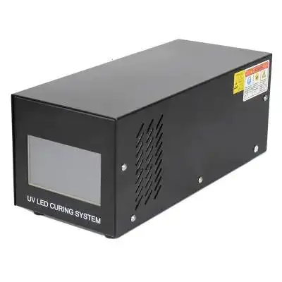
UVET uses active fan cooling, which supports more stable operation during repeated production cycles. This becomes particularly relevant when Precision Assembly Curing is performed continuously rather than as an occasional laboratory process.
However, process validation should still compare measurements at three states:
- Before curing;
- Immediately after full cure;
- After fixture release and thermal stabilization.
A component that remains aligned while clamped may move once stored elastic energy is released.
UVET Specifications in a Precision Assembly Context
UVET provides several production-relevant characteristics that can be applied directly to optical bonding process design.
| UVET Capability | Relevance to Precision Assembly Curing |
| 50 × 30 mm irradiation field | Can expose several bonding points or compact optical modules simultaneously |
| 365 nm up to 3500 mW/cm² | Supports UV-sensitive adhesive systems requiring shorter-wavelength activation |
| 385/395/405 nm up to 4200 mW/cm² | Provides alternative spectral options for different adhesive and substrate combinations |
| Active fan cooling | Helps stabilize lamp operation during continuous cycles |
| Instant LED on/off | Supports controlled tack-cure and final-cure sequences |
| Standalone or automated integration | Allows curing position and timing to be incorporated into production equipment |
The value of these specifications is not the numbers alone. Their importance lies in how they support a repeatable Precision Assembly Curing process for a defined optical joint.
Validate Optical Performance, Not Just Adhesive Hardness
A process should not be accepted simply because the adhesive is tack-free.
For precision optical assemblies, validation should include:
• Decenter and tilt before and after cure;
• Focal position or MTF where applicable;
• Beam pointing or coupling efficiency;
• Dimensional change after fixture release;
• Thermal-cycle stability;
• Evidence that all shadow-sensitive regions completed curing.
Applicable optical tolerancing can be referenced against the ISO 10110 family, while UV radiation safety should be evaluated using the relevant photobiological safety requirements.
Building a Stable Precision Assembly Curing Process
Reliable Precision Assembly Curing comes from controlling the complete mechanical and photochemical transition from alignment to final bond stability. Adhesive geometry, cure sequence, fixture stiffness, thermal behavior, UV access, and final optical verification all matter.
With a 50 × 30 mm curing area, four wavelength options, output up to 4.2 W/cm², active fan cooling, instant LED control, and flexible production integration, UVET provides a practical platform for optical and optoelectronic bonding processes.
For manufacturers developing high-accuracy assemblies, UVET can support the evaluation of curing area, joint accessibility, wavelength selection, and staged exposure strategy so that the curing process protects the optical alignment already achieved upstream.
FAQs
Q1. What optical bonding applications does UVET accommodate?
UVET's UV LED curing modules can be used for a variety of assembly applications and bonding processes such as lens bonding, assembly of optical sensors, optoelectronics, construction of imaging systems, and other precision adhesive bonding. The curing configuration will depend on geometry of the joints, type of adhesive and access of UV to the joint.
Q2. What makes UVET suitable for precision assembly curing?
For precision assembly curing, UVET has 50 × 30 mm irradiation area and instant on/off fan cooled LEDs providing multiple UV wavelengths and 4.2 W/cm² irradiance. Controlled tack curing and final curing for accurate assembly processes is made possible by a combination of these features.
Q3. What UV wavelengths for precision assembly curing does UVET have?
UVET offers a choice of 365 nm, 385 nm, 395 nm and 405 nm. This enables process engineers to choose according to the photoinitiator in the UV adhesive, the optical material, and the required cure depth.
Q4. What UV intensity can UVET provide?
At 365 nm, UVET offers 3500 mW/cm² while at 385 nm, 395 nm and 405 nm, it can go up to 4200 mW/cm². This should not be the maximum setting and should be set based on adhesive behavior and stability of components being assembled.
Q5. How does UVET’s 50 × 30 mm area help for optical assembly?
UVET’s 50 × 30 mm irradiation area is able to cure adhesive areas which are proximally located on a compact lens, sensor, module or other optical elements thus reducing the asymmetric forces which may be caused by a sequential curing process.


