
Uniform UV Intensity: The Key Factor for Reliable UV Adhesive Curing Performance
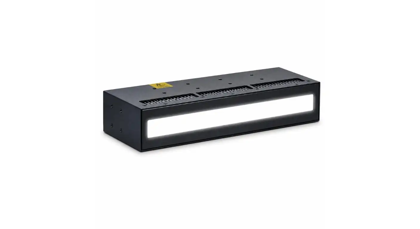
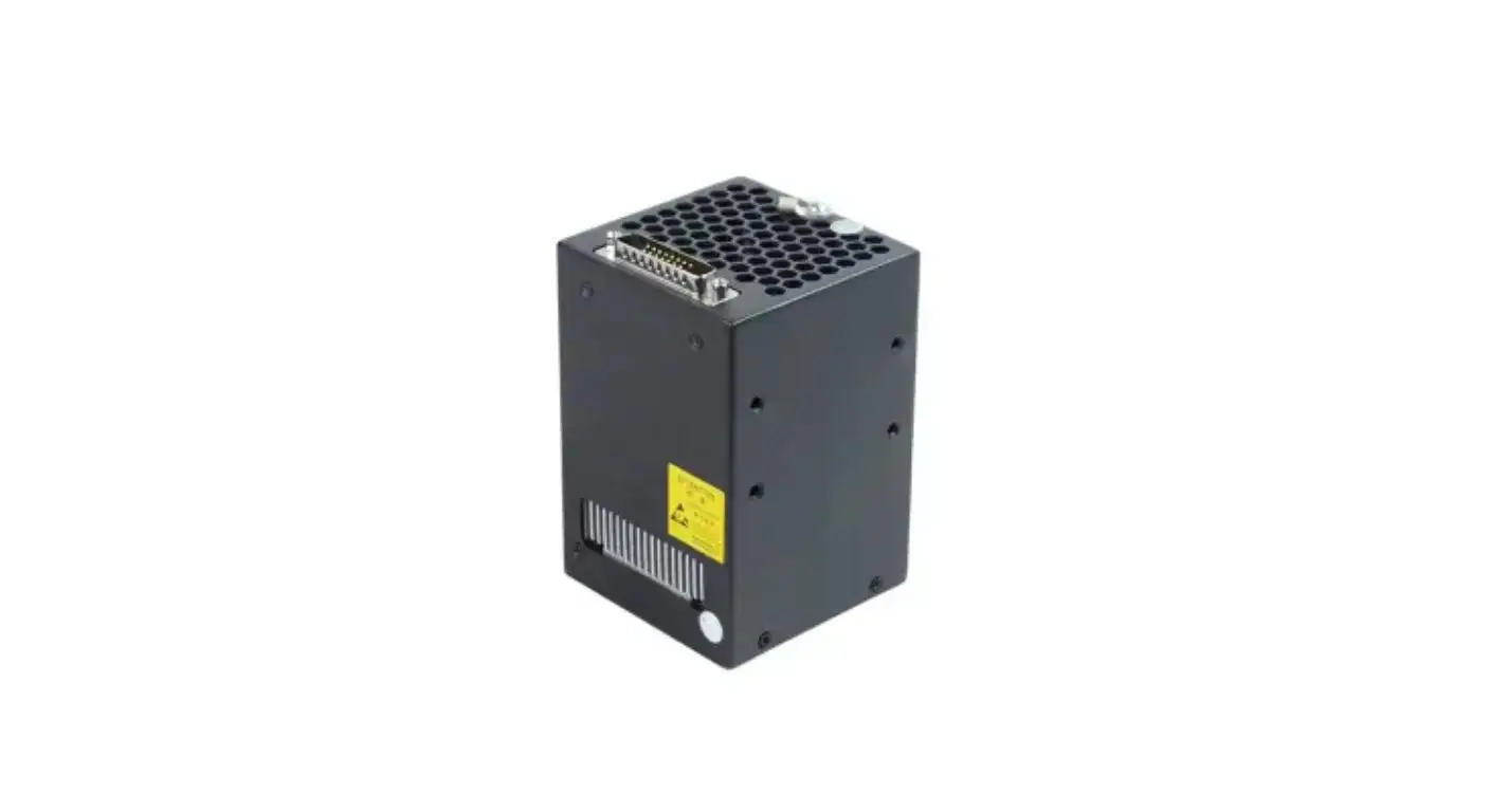
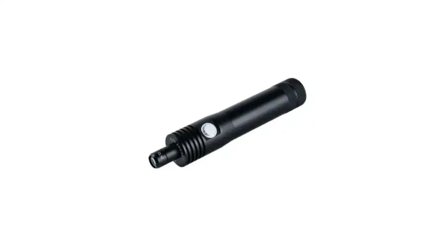
In UV adhesive bonding, high irradiance can shorten cure time, but it does not automatically produce a reliable bond. If the center of a work area receives substantially more UV energy than its corners, components processed in the same cycle can develop different degrees of conversion, cure depth, and final mechanical strength.
For this reason, Uniform UV Intensity is one of the most important parameters in a repeatable UV adhesive curing process. It determines whether every critical point on a component receives enough energy to remain inside the validated curing window—not simply whether the lamp can achieve a high peak W/cm² value.
What Uniform UV Intensity Actually Measures
Uniform UV Intensity describes the spatial consistency of irradiance across the effective curing area.
A practical expression is:
UV Intensity Uniformity = Imin / Imax × 100%
If nine measurement points across a curing zone produce a maximum of 820 mW/cm² and a minimum of 750 mW/cm²:
Uniformity = 750 / 820 × 100% ≈ 91.5%
This number is more useful than a single center-point reading because adhesive joints normally occupy an area rather than one optical measurement point.
| Process Variable | Engineering Significance | Main Risk if Uncontrolled |
| Irradiance, W/cm² | Instantaneous UV power | Cure rate becomes too low or aggressive |
| Dose, J/cm² | Total delivered UV energy | Under-cure or unnecessary overexposure |
| Uniform UV Intensity | Spatial energy consistency | Position-dependent bond quality |
| Wavelength | Photoinitiator activation | Insufficient polymerization |
| Working distance | Irradiance and beam overlap | Hot spots or weak edge regions |
For production engineers, the useful question is therefore not "What is the maximum UV intensity?" but "What UV intensity reaches the worst-case part location?"
Why Uneven Intensity Creates Uneven Adhesive Performance
UV adhesives cure when photoinitiators absorb radiation and generate reactive species that initiate polymerization. If irradiance changes significantly across the bond line, the polymerization history also changes.
Low-energy regions can experience:
• Slower gelation and conversion;
• Lower effective crosslink density;
• Residual uncured or partially reacted material;
• Reduced shear and peel strength;
• Greater sensitivity to humidity or thermal cycling.
Consider a process requiring at least 8 J/cm².
The relationship is approximately:
UV Dose = Irradiance × Exposure Time
For a 10-second curing cycle:
| Location | Irradiance | Calculated Dose | Process Result |
| Center | 1.00 W/cm² | 10.0 J/cm² | Above requirement |
| Mid-zone | 0.85 W/cm² | 8.5 J/cm² | Within process window |
| Edge | 0.70 W/cm² | 7.0 J/cm² | Under-cure risk |
Although the nominal process appears to deliver sufficient UV energy, the edge joint does not reach the specified dose.
This is why Uniform UV Intensity directly affects batch repeatability.
More Exposure Time Does Not Fix Poor Uniformity
A common response to under-cure is to extend curing time. This can increase the minimum dose, but it does not correct the underlying irradiance distribution.
If the previous cycle increases from 10 to 12 seconds:
• Center dose rises from 10 to 12 J/cm²
• Edge dose rises from 7 to 8.4 J/cm²
The weakest location now passes, but the center receives approximately 43% more dose than the edge.
Depending on adhesive chemistry and substrate sensitivity, excessive exposure may increase temperature, accelerate yellowing, alter surface properties, or simply reduce process efficiency.
A more stable strategy is:
- Improve uniform UV intensity;
- Confirm wavelength compatibility;
- Establish the minimum acceptable irradiance;
- Optimize exposure time after spatial variation is controlled.
What Causes UV Intensity Variation?
LED Optical Overlap
A UV LED array contains multiple emitting sources. At short working distances, individual beam profiles can create localized high-intensity regions. Increasing distance generally improves beam overlap, but irradiance decreases.
Therefore:
• Short distance → higher irradiance, potentially poorer overlap
• Longer distance → improved overlap, lower irradiance
The optimum working distance should be established by mapping the complete exposure plane rather than measuring only its center.
Edge Loss and Chamber Geometry
Open UV systems tend to lose useful energy at the boundaries of the irradiation area. Reflective chamber surfaces can redirect a portion of this radiation toward side walls, component edges, and other regions receiving less direct exposure.
This is particularly relevant when curing:
• Multiple parts in one batch;
• Tall or vertically oriented assemblies;
• Components with side-facing adhesive joints;
• Irregular geometries that create partial shadowing.
Why Reflective Chamber Curing Changes the Optical Environment
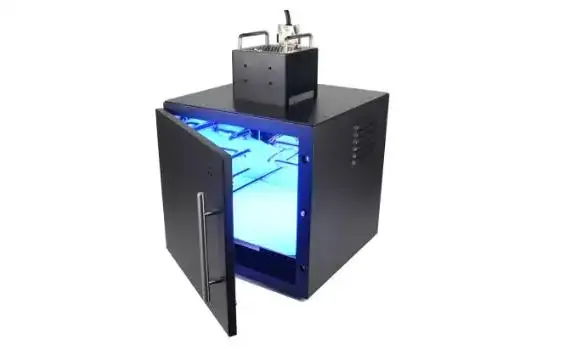
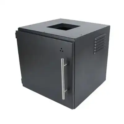
UVET uses a reflective internal chamber structure to promote more distributed UV exposure. Rather than relying only on direct line-of-sight radiation, reflected energy contributes secondary exposure inside the curing volume.
The system provides a 300 × 300 × 300 mm internal working space within an overall housing of approximately 360 × 360 × 360 mm. The cubic curing volume is large enough to accommodate either a larger assembly or multiple smaller components while keeping the optical environment enclosed.
This arrangement is especially useful when Uniform UV Intensity must be maintained across a batch rather than across a single flat sample.
| Chamber Design Element | Effect on Curing Process |
| 300 × 300 × 300 mm curing volume | Supports larger components or multi-part batch layouts |
| Reflective internal surfaces | Redistribute UV toward edges and secondary surfaces |
| Adjustable shelves | Control part height and lamp-to-part distance |
| Multiple UV LED lamp configurations | Allows light source selection according to process requirements |
| Anti-UV leakage viewing window | Enables process observation while limiting direct UV exposure |
| Door-linked operation | Lamp starts after closing and stops immediately if opened |
The last feature is not simply an operating convenience. The interlocked door helps prevent an interrupted or incorrectly exposed batch from continuing unnoticed while also supporting safer enclosed operation.
Shelf Position Is a Curing Parameter, Not Just a Mechanical Adjustment
UVET's adjustable shelf system provides flexibility for different part heights, but its more important function is controlling optical geometry.
Changing shelf height changes:
Lamp-to-part Distance → Irradiance → Beam Overlap → UV Dose
For example, placing a product closer to the UV source may increase irradiance but produce greater spatial variation. Moving it farther away may improve Uniform UV Intensity, although additional exposure time may then be required.
For production qualification, each commonly used shelf position should therefore be validated independently.
Wavelength Must Still Match Adhesive Chemistry
Even excellent Uniform UV Intensity cannot compensate for the wrong spectral output.
The photoinitiator must absorb the selected UV LED wavelength efficiently. Cure behavior is also affected by:
• Adhesive thickness;
• Pigments and fillers;
• Optical transmission of the substrate;
• Adhesive absorption coefficient;
• Joint geometry.
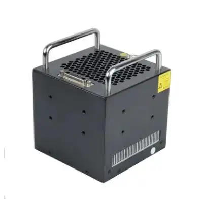
UVET's chamber can be configured with different UV LED lamp solutions, allowing the optical source to be selected according to the adhesive, ink, coating, or assembly process rather than forcing every application to use one fixed lamp arrangement.
How to Validate Uniform UV Intensity in Production
A useful qualification method is a 3 × 3 radiometer map across the actual curing plane.
Measure nine locations and record:
• Peak irradiance;
• Accumulated UV dose;
• Minimum and maximum readings;
• Average intensity;
• Intensity variation between center, edge, and corners.
If a 300 mm × 300 mm plane records:
Imax = 820 mW/cm²
Imin = 750 mW/cm²
then:
Uniform UV Intensity = 91.5%
The same mapping should be repeated after changing shelf height, lamp configuration, or production loading.
Radiometry should then be correlated with actual process results such as bond strength, tack-free state, dimensional stability, or functional testing. The lowest-intensity qualified position should define the process capability—not the highest measured value.
Building a More Repeatable UV Adhesive Curing Process
Reliable UV curing depends on controlling the complete optical process:
• Match the UV source to adhesive photochemistry;
• Map uniform UV intensity across the usable work area;
• Define minimum acceptable dose at the weakest location;
• Control working distance and shelf position;
• Account for shadowing caused by component geometry;
• Maintain consistent batch loading and orientation.
For electronics, precision assemblies, printed components, prototypes, and small-batch production, an enclosed reflective chamber provides greater control over these variables than relying solely on nominal lamp output.
UVET's configurable UV LED curing chamber combines a 300 × 300 × 300 mm curing volume, reflective light distribution, adjustable positioning, multiple lamp configuration capability, UV-protected viewing, and door-interlocked operation. For manufacturers developing a process where curing consistency is more important than peak intensity alone, UVET can support evaluation of chamber layout, light-source configuration, working distance, and Uniform UV Intensity around the actual application requirements.
FAQs
Q1. What does the term Uniform UV Intensity mean for UV adhesive curing?
This term describes the distribution of UV energy that falls across the entire area of the curing zone. Higher uniformity reduces the difference that parts in the center, edges, and corners receive.
Q2. Why is Uniform UV Intensity important for UV adhesive bonding?
Inconsistent distribution of UV energy causes some areas of an adhesive to be fully cured while other sections of the adhesive remain partly cured. Improving uniformity enables uniform curing and consistent polymerization and bond strength.
Q3. How does UVET improve the distribution of UV energy in its curing chamber?
UVET defines the reflective surfaces in the curing chamber. Energy that reflects provides secondary irradiation to the edges and surfaces that are not directly opposite the source. Reflectivity aids uniform exposure of multiple or irregularly shaped components.
Q4. What is the processing volume of UVET’s UV LED curing chamber?
UVET has a chamber internal curing space of 300 × 300 × 300 mm and an external dimension of approximately 360 × 360 × 360 mm. The chamber can handle a large assembly and/or multiple smaller components for batch curing.
Q5. Can the components that are of different heights be processed in the curing chamber of UVET?
Yes, the processing chamber has adjustable shelves and can be set according to component dimensions and processing requirements. Shelf height affects lamp-to-part distance, which also affects uniformity, dosage, and irradiance.


