
Building a Scalable Modular Area UV System for Industrial Printing
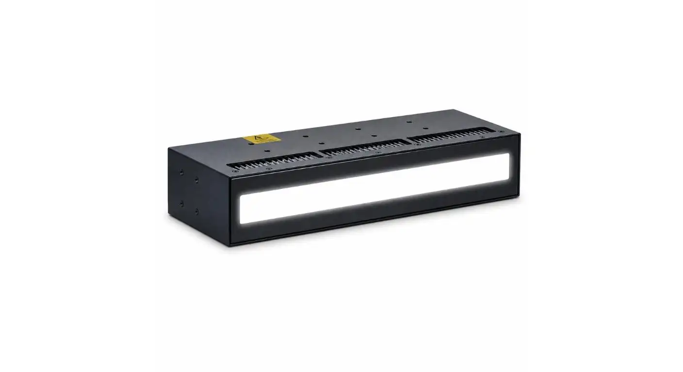
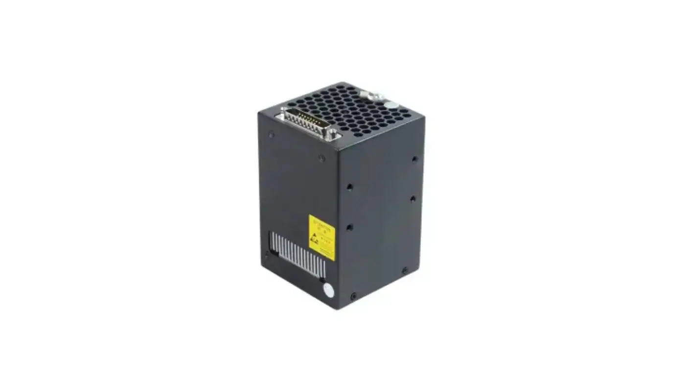
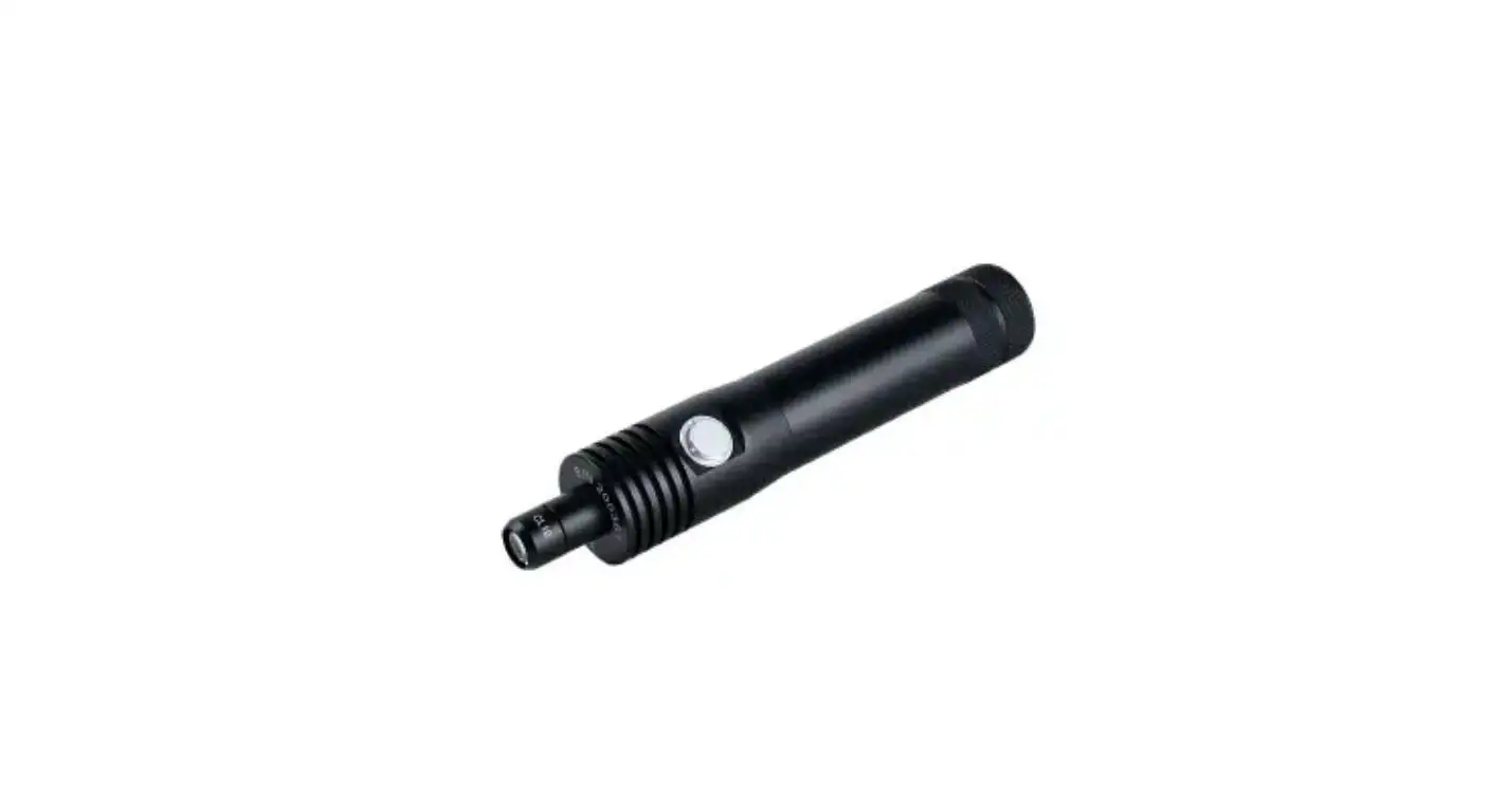
It is not possible to reliably achieve a wider curing area with a number of lamps side by side without testing the combined output of the lamps. The system can generate a single, uniform curing zone or a series of distinct energy bands which are visible, depending on module spacing, optical overlap, cooling and control timing.
A modular area UV system should enable to increase the curing width without any change in the adhesion and surface finish of the printed image for the printer manufacturers and system integrators. It is important that the system be designed as a single curing platform rather than a number of individual UV lamps.
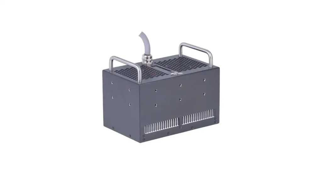
Begin on the Required Curing Width.
The first step is to define useful print width, rather than just physical width of the printer. Record the width of the largest image, the printhead layout, the position of the UV source and the distance between the UV source and the substrate.
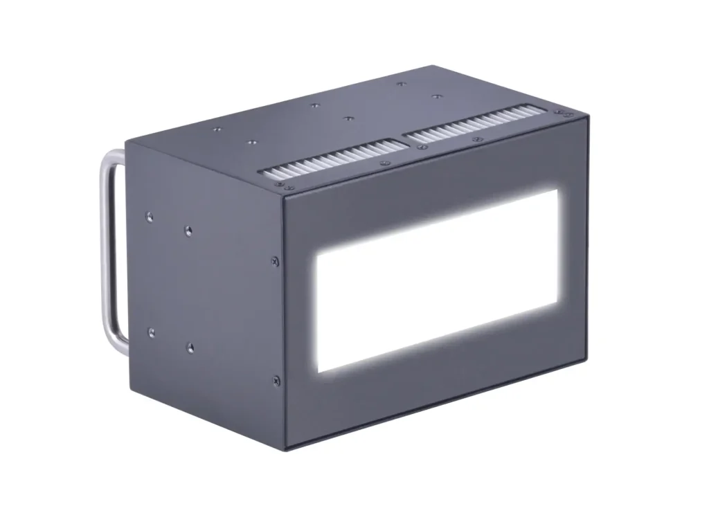
For inkjet application the UV LED system UVET is available with an irradiation area of 150 × 40 mm. The small size allows for curing around the print area without having to install a much bigger lamp than necessary for the application.
If more than a single module is employed, then the total useful curing width should be computed, taking into account optical overlap. The nominal widths would only sum up to an error with the edge intensity of each module being different from the central output.
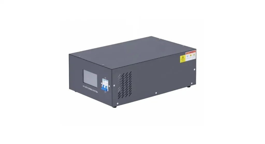
Consider Module Joints to be Critical Curing Zones.
The most crucial parts of a modular system are the connections between individual UV units. If there is insufficient overlap, there will be a low-energy strip; if there is too much overlap, then there will be a high-energy band.
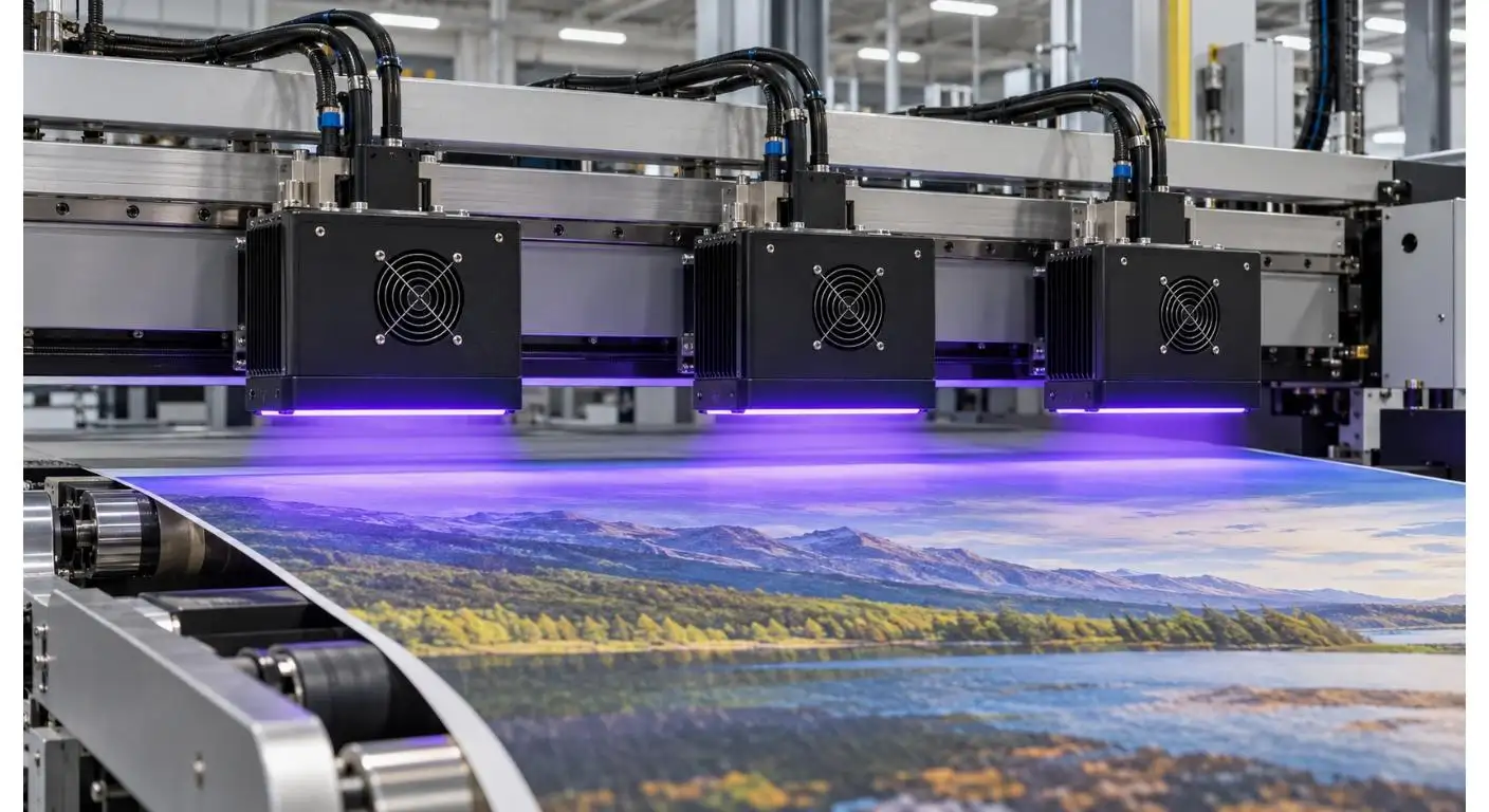
These differences can be seen as under cured or over cured products, variations in gloss or lines within a printed image. It is more evident on uniform colors, varnished surfaces and on high speed passes.
Draw a map of the overall irradiance over the curing width at the actual working distance. The center of each module, the two edges and all overlap areas should be measured. Mechanical adjustment should be made prior to final curing parameters being approved.
| Joint Condition | Likely Print Effect | Required Check |
| Insufficient overlap | Under-cured strip | Edge irradiance |
| Excessive overlap | Gloss or hardness band | Combined peak output |
| Unequal module angle | Irregular curing width | Lamp alignment |
| Different working distances | Output variation | Mounting height |
| Module output mismatch | Repeating print bands | Individual UV readings |
Connect Wavelength and Output to the Ink.
Requirements for modularity do not do away with the need for spectral compatibility. The wavelength for each module should be the same as the photoinitiator of the UV ink, varnish or coating.
It comes in 365, 385, 395 and 405 nm wavelengths. It states a max intensity of 14 W/cm² for the 385, 395 and 405 nm versions; and 10 W/cm² for the 365 nm version.
Test the wavelength with the ink manufacturer and then test it with the product to be printed. The UV dose required may vary due to changes in ink color, deposited thickness, pigment loading and reflectivity of the substrate. A thin clear varnish setting might not adequately set a thick, opaque ink.
The company’s UV LED curing systems for printing cover UV inkjet, label, packaging, film and other printing applications.
Match up the output of the UV coating with the speed of the print.
As the print or conveyor speed increases the value of the UV energy in the substrate decreases. A system set up for a slow speed of a trial run might not be sufficiently cooked at a normal production rate.
Take tests for minimum, standard and maximum production speeds. For each speed, determine adhesion, surface tack, rub resistance and if applicable, other specifications pertaining to the printed product.
The system is equipped with a UV power adjustment function that enables it to adapt to various inks and materials while reducing the output power of the UV lights when they aren't needed. For each recipe approved, it is necessary to establish a wavelength, a power setting, a working distance, number of passes and production speed.
The cooling system is stabilized across all modules.
The UVET inkjet system is a fan cooling system. A modular arrangement requires adequate ventilation for all lamps whether they are placed under machine covers or frame members.
Limited airflow can cause fluctuations in the level of output and higher operating temperature. When the adjacent modules are releasing warmed air towards each other, the middle part of the array could be hotter than the rest.
Check the mounting frame for air inlet clearance and exhaust direction and access to the filter before finalizing the frame. Temperature and irradiance should be measured after the system has been in operation for a sufficient period of time to attain production stability.
Use the Modules as One Controlled System.
No one lamp should flash or turn on at different times when the printed product enters the curing area. The delay of triggering, power setting and exposure time should be synchronized with the printer/PLC.
The mounting structure should be able to keep the module position, angle and working distance without any changes during machine vibration and maintenance. Cabling, cooling paths and electrical connections should not be made impassible or cause optical alignment to change.
UVET's OEM and ODM services are available for projects that need a customized dimension, controls or mechanical integration. The mounting frame and electrical interface need to be determined prior to defining system requirements.
| Integration Item | Information to Record | Purpose |
| Module position | Order and mounting location | Support maintenance tracking |
| Trigger timing | Start and stop delay | Synchronize with printing |
| Power recipe | Setting for each approved job | Maintain curing consistency |
| Cooling clearance | Air inlet and exhaust space | Prevent heat accumulation |
| Working distance | Lamp-to-substrate distance | Preserve UV distribution |
| Safety interlock | Shutdown response | Protect operators and equipment |
The validation of the entire curing width is performed.
For a modular area UV system, a single measurement is not enough in the middle of the system. Left edge, overlap zones, right edge, and module centers are all areas to be covered by the validation.
Print a test image on the entire width and check the image under the same conditions. Check the degree of adhesion, surface tack, scratch resistance and gloss at various positions.
Repeat the test after running continuously. To verify that there is no imbalance between cooling and output once the equipment has come to normal operating temperature.
Outline a plan for maintaining the module.
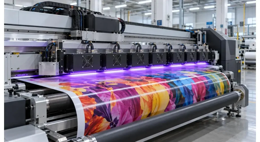
Maintenance can be simplified by modularity as one part of the curing assembly can be inspected and serviced without the need for replacing the entire assembly. A replacement module will need to be the same output and alignment as the other modules, though.
Cleaning of optical windows, checking of fans, checking of mounting points and measuring of UV output should be part of the maintenance program. Note where and how each module has changed and measure the result of each change to find out whether it is gradual or sudden.
Once a module is replaced and/or repositioned repeat the irradiance map on the module over the module joint. Avoid using the same model numbers as being equal to the same overlap pattern.
Conclusion
A modular area UV system must be scalable, while maintaining a uniform curing width, no low-energy gaps and uniform module temperatures. The critical factors for successful integration are optical mapping, wavelength compatibility, coordinated control and balanced cooling.
Determine the necessary curing width first, confirm all the module joints and approve the settings at the actual production speed. This allows for a scalable UV curing system that allows for the use of wider printing equipment without compromising print quality.
FAQs
Q1. What is a modular area UV system?
It is a UV curing system that utilizes compact UV LED modules and arranges them to be able to cure the required area. This setup may be modified for various widths of printers and different spaces for installation.
Q2. What is the reason to have overlap between the modules of the UV?
The technique of overlapping shields against small gaps in the high intensity of light created by two or more lamps. Care needs to be taken with it as it can also result in high energy bands if too much of it overlaps.
Q3. What wavelength is there to choose for UV inkjet printing?
The right wavelength needed is dependent on the photoinitiator of the UV ink. Typically 365, 385, 395 and 405 nm are used, however it is advisable to check compatibility with the ink supplier.
Q4. Are different power settings possible for the modules?
The output may be variable but when using adjacent modules, it is usually necessary to have balanced output to prevent any visible difference in the curing. Final settings will need to be checked over the full width of the print.
Q5. When is remapping of the system appropriate?
Remapping should be done when a module has been changed, its position changed, its working distance or cooling system changed. It should also be part of the periodic process verifications.


